12 best current sensors
Current sensors, also known as current transducers or current probes, are electrical devices used to measure and monitor the flow of electric current in a circuit. They play a crucial role in various applications, including electronics, power systems, and industrial processes. Here's what you should know about current sensors:
Purpose: Current sensors are designed to measure the magnitude and direction (AC or DC) of electrical current in a conductor without physically breaking the circuit. They are used to monitor and control electrical systems and devices.
Types: There are several types of current sensors, each designed for specific applications:
Hall Effect Sensors: These sensors use the Hall Effect principle to measure the magnetic field generated by the current passing through a conductor. They are suitable for both AC and DC current measurements.
Current Transformers (CTs): CTs are passive devices that consist of a primary winding (conductor) and a secondary winding. They are commonly used to measure high AC currents, such as those in power distribution systems.
Rogowski Coils: Rogowski coils are flexible, coil-shaped sensors used to measure AC current. They are particularly useful in applications where it's challenging to use rigid CTs.
Shunt Resistors: Shunt resistors are low-resistance elements placed in series with the current path. The voltage drop across the shunt resistor is proportional to the current flow, allowing for current measurement.
Clamp-On Sensors: These sensors feature a split-core design that can be clamped around a conductor without disconnecting it. They are convenient for quick measurements in existing circuits.
Measurement Range: Current sensors come in various measurement ranges, from milliamps (mA) to thousands of amps (kA), depending on the application. Selecting the appropriate range is crucial for accurate measurements.
Output: Current sensors provide output signals that are proportional to the measured current. This output can be analog (voltage or current), digital, or a communication protocol like Modbus or RS-485, depending on the sensor type.
Accuracy and Resolution: The accuracy and resolution of current sensors vary based on their specifications and intended use. High-precision sensors are essential for applications where precise measurements are critical.
Safety: When working with current sensors, it's crucial to follow safety precautions, especially in high-voltage applications.Ensure proper insulation and grounding to prevent electrical hazards.
Applications: Current sensors find applications in various fields, including:
- Power distribution and monitoring
- Motor control and protection
- Renewable energy systems (e.g., solar and wind)
- Industrial automation and control
- Battery management systems
- Electrical safety and fault detection
Calibration and Maintenance: Regular calibration and maintenance are necessary to ensure the accuracy and reliability of current sensors. Calibration should be performed according to the manufacturer's guidelines.
Current sensors are essential components in electrical systems and automation processes, allowing for precise monitoring and control of current flow. Choosing the right type and specification of current sensor is crucial for the accuracy and safety of electrical measurements and operations.
Below you can find our editor's choice of the best current sensors on the market
JANSANE SCT-013-030 30A Non-invasive AC Current Sensor Split-Core Current Transformer
Product description
Specification
Model: SCT-013-030
Core Material: Ferrite
Input Current: 30a AC
Leading Wire in Length: 1.5m
Opening Size: 0.51 * 0.51inch / 13 x 13mm
Turns Ratio: 1: 1800
Resistance Grade: Grade B
Max Sampling Resistance: 10 Ω
Linearity: ±3%
Accuracy: ±1%
Work Frequency: 50-1 KHz
Work Temperature: -25˚C ~ 70˚C
Reference project: Open Energy Monitor
Dielectric Strength: 6000V AC/1min
Two Form of Output: current output or voltage output (voltage output built-in the sampling resistor);
Mechanical strength: opening and closing times, no less than 1000 times (20 ℃) High Quality and Safe: Meet the requirement of flame-retardant characteristics (UL94-V0)
- This SCT-013-030 ac current sensor used for measuring alternating current, particularly used for whole building consumption or generation.
- This split core current transformer is particularly suitable for DIY use and it works well with arduino and raspberry pi.
- Use this 30a current sensor to build your own energy monitor, reducing your power usage, or use it build an over-current protection device for an AC load.
- Input Current: 30a AC; Length of Leading Wire: 1m; Two Form of Output: current output or voltage output (burden resistor needed to add); Cable Jack: 3.5mm (like a headphone jack).
- Suitable for lighting equipment, AC motors, air compressors, monitoring, current measurement and over-current protection.
User questions & answers
| Question: | what range of burden resistor is needed |
| Answer: | Depends on what output you need for your device. If I am doing my math correctly this device has 50ma output max. So (.050a x 100ohm) = 5v. This would give you a 0-5v for 0-100a reading. I believe, but could be wrong. |
| Question: | is there a model for DC current using hall effect |
| Answer: | Yes, YHDC also make a range of Hall Effect DC current sensors. The 200A version is at the link that follows -- https://www.amazon.com/gp/product/B076DVLSRD/ref=ppx_yo_dt_b_search_asin_title?ie=UTF8&psc=1 |
| Question: | Do i need a rectifier to measure the ac voltage with a node mcu input or the adc 1115. the drawing in the description doesn't show one for theadc |
| Answer: | Yes. This is a transformer so it produces AC. If you want to measure it on a DC microprocessor input pin, you need to rectify it. |
| Question: | What does 1v mean |
| Answer: | 1V means 30A. Search for the device data sheet to see the various voltage to Amperage readings. 0.5V is ~15A (+- 1%). |

CrocSee Miniature Current Switch, CS-TS0, Normally Open Amp Sensor Monitoring Relay, AC 1-50A Detectable
Product description
CrocSee AC Current Switch is designed for AC current monitoring, motor overload protection, automatic control system and other applications. This device senses a current draw of between 1amp and 50 amps and closes a set of contacts while AC current is passing through sensor.
Main Specifications:
Enclosure Dimensions(LxWxH): 88 x 25 x 50mm; Or approx. 3.46 x 0.98 x 1.97 inch
Sensor Hole Diameter: 20mm (0.79 inch)
Mounting Holes: 2x5mm holes spaced 76mm on base (2 x 0.19”holes spaced 3”on base)
Voltage Range: 120-240VAC
Switch Rating: 2.5 A @ 120 VAC/240VAC (Only works with AC current, not for DC current)
Contact Type:Normally Open
Operating Temperature: -20 to 45℃(-4 to 113℉)
Humidity Limits: 0-95% RH, non-condensing
Response Time: ≤200ms
Accuracy: 1%
Hysteresis: ≤1%
NOTE:
1. Disconnect and lock-out all power sources prior to installation.
2. The current switch has a rating of 2.5 Amps maximum. If the secondary device (which is conncted with the switch) draws more than 2.5 Amps, then you will need a separate high current relay.
3. A load must be applied across the NO switch to work. If no load is applied across the NO switch, these NO terminals will not close with correct operating primary current.
4. The switching current is NOT calibratable. However, it is sensitive enough to detect any current draw of between 1amp and 50 amps.
Package includes:
1x AC Current Switch
1x Instruction Manual
Warranty:
1-year free replacement or full refund without return.
If the item you have received is defective in any way, please message us for free replacement or refund without return.
- N.O. Universal Outputs: 2.5A @ 120 VAC/240VAC; In 240V circuit, only one 120V hot line is connected.
- Self-powered, no external power supply required
- Accurate & Dependable: Offers a sensing range of 1 to 50 amps and universal, solid-state outputs; Accuracy: 1%
- Faster Response Time: Once current flow is detected, it closes a set of contacts immidiately; Response Time: ≤200ms
- NOTE: If you want to test the operation of the sensor switch, a load must be applied across the NO contacts; otherwise, it will not work.
User questions & answers
| Question: | Will this work switching 1a @ 240vac |
| Answer: | Yes, it will work switching 1a @ 240vac, but only loop one HOT power wire trough the current sensor. |
| Question: | Is the sensing current adjustable |
| Answer: | No. |
| Question: | Need this to sense ac current and switch 12v dc. Will this work |
| Answer: | It has a dry set of contacts which close when sensing 1 to 50amps a/c, so weather you are switching a/c or d/c it doesn’t matter as long as you don’t exceed its current rating which is 2.5 amps. |
| Question: | Would this be able to control the secondary load at 1A @240vac or is that too much for the unit |
| Answer: | Yes, this current switch is able to control the secondary load at 1A @240vac. In 240V circuit, only one 120V hot line is connected. Also, if the current being meaured is less than 1A, loop the wire through the sensor coil to incease the current field. Cross-core current = actual current X number of loops around sensor coil e.g. If the current draw from the measured device is 0.5 amp, then loop the wire around the sensor coil 3 times and it will produce 1.5A current. |

HiLetgo Analog Current Meter Sensor Module AC 0~5A Ammeter Sensor Board Based on TA12-100 for Arduino
HiLetgo
Product description
Specification:
Interface: 3PIN
Power Supply: 5V
Size: 30x 24x 1.6mm
Weight: 25g
Electrical characteristics:
Transformation coefficient: 1000:1
Input current: 0--5A
Output current: 0--5mA
Sampling resistor: 200Ω
Sampling voltage: 0--1V
Working frequency: 20-20000Hz
Working temperature: -55--85℃
Dielectric strength: 6KAC/1min
Package Include:
1* Analog Current Meter Sensor Module Board
If you need detail schematic, please contact us
User questions & answers
| Question: | What would happen if I seriously overranged this (say 15 amps through it)? I want to know if an air conditioner is on, not concerned about accuracy |
| Answer: | I have a similar situation: I am using it to measure up to 15 amps BUT I split the wire in three so the current flows equally through them and I measure only one of the wires. |
| Question: | Where is the data sheet for this product? in particular, what to the output pin labels "g", "n", and "s" refer to |
| Answer: | I found a basic tutorial that include wiring schematic and Arduino code for the subject item, that could be helpful,... Title: "TA12-100 Arduino AC Current Sensor Tutorial" it is available at: http://henrysbench.capnfatz.com/henrys-bench/arduino-current-measurements/ta12-100-arduino-ac-current-sensor-tutorial/ - Have a nice day,... |

Electronics-Salon Panel Mount AC/DC Current Sensor Module Board, Based on ACS712 (+/-20Amp)
Electronics-Salon
Product description
Datasheet: https://images-na.ssl-images-amazon.com/images/I/81CRdUi0xWL.pdf
The item provides economical and precise solutions for AC or DC current sensing in industrial, commercial, and communications systems. Typical applications include motor control, load detection and management, switched-mode power supplies, and overcurrent fault protection. The device is not intended for automotive applications.
Output voltage proportional to AC or DC currents.
FR-4 fiber glass PCB, dual copper layers.
100% new, never used.
Electrical Parameters:
Load Maximum Current: +/-5Amp, +/-20Amp and +/-30Amp selectable.
Load Frequency Bandwidth: DC ~ 80 kHz.
Minimum Isolation Voltage: 2.1 kV(RMS).
Operating Voltage: Regulated 5VDC, or 8 ~ 35VDC.
Operating Current: 20mA(max).
- Load Maximum Current: +/-5Amp, +/-20Amp and +/-30Amp selectable. Panel Mount Version.
- The item provides economical and precise solutions for AC or DC current sensing in industrial, commercial, and communications systems. Typical applications include motor control, load detection and management, switched-mode power supplies, and overcurrent fault protection. The device is not intended for automotive applications.
- Output voltage proportional to AC or DC currents.
- FR-4 fiber glass PCB, dual copper layers.
- Datasheet: https://images-na.ssl-images-amazon.com/images/I/81CRdUi0xWL.pdf
User questions & answers
| Question: | Could you explain this parameter: load frequency bandwidth dc ~ 80 khz |
| Answer: | Yes, DC to 80 kHz bandwidth |
| Question: | Could you explain this parameter: load frequency bandwidth dc ~ 80 khz |
| Answer: | The item can support DC or AC. |
| Question: | When measuring a 60 hz ac circuit, will the dc output be constant if the ac current is constant or does it cycle around 2.5 vdc at 60 hz |
| Answer: | Cycle around 2.5 vdc at 60 hz |
| Question: | whut is max voltage on pins P+ and P |
| Answer: | Voltage doesn't matter. Those two IP+ IP- sense current that pass across the Load. |

SCT-013-000 Non-invasive AC Current Sensor Split Core Transformer 100A
CTYRZCH
Product description
Specification:
Model: SCT-013-000
Type: Non-invasive current transformer
Core Material: Ferrite
Input Current: 0~100A AC
Output Mode: 0~50mA
Leading Wire in Length: 1m
Turns Ratio: 1: 1800
Work Voltage: 660 v
Resistance Grade: Grade B
Max Sampling Resistance: 10 Ω
Linearity: ±3%
Accurancy: ±1%
Work Frequency: 50-1 KHz
Work Temperature: -25˚C ~ 70˚C
Reference project: Open Energy Monitor
Dielectric Strength: 6000V AC/1min
Opening Size: 0.51 * 0.51inch / 13 x 13mm
Two Form of Output: current output or voltage output (a burden resistor needed to add);
Mechanical strength: opening and closing times, no less than 1000 times (20 ℃)
High Quality and Safe: Meet the requirement of flame-retardant characteristics (UL94-V0)
Applications:
For AC motors, lighting equipment, air compressors and other current measurement,monitoring and protection.
Package include:
2 PCS Split Core Current Transformer SCT-013-000
Insruction
100% Satisfaction Guarantee:
12-Month Warranty; No satisfied ,Free reason for return; We could also resend you new one due to quality problem.
- The lead length is 1.5 meters, the standard Φ3.5 three-core plug output
- Non-linearity ±3% (10%~120% rated input current), two output forms of current and voltage.
- Opening size: 13mm×13mm, fully compatible with most similar products; working temperature: -25℃~+70℃
- [Ferrite Mechanical strength] - The number of opening and closing times is not less than 1000 (tested at 20℃)
- [Applications] - Used for current measurement, monitoring and protection of AC motors, lighting equipment, air compressors, etc.
User questions & answers
| Question: | Is the burden resistor required to be added before clamping the connection to the "mains" wire |
| Answer: | No, these are parasitic coils with no “connection” to the mains wire whose current is being measured. You will need to use a known burden resistor to enable measuring the output current. Be sure your expected peak current is well within the specs. |
| Question: | Is it normal for the sensor to buzz when installed on the wire? mine buzzes with about 6a at 240vac passing through the wire it's clamped on |
| Answer: | Normally it will not. However, if the leaves of the iron core have not gotten enough lacquer through them, they WILL buzz a bit. It should not be a problem...just an annoyance. |
| Question: | Does anyone have a sample circuit? What's the value of R |
| Answer: | There are values in the data sheet, search the web, |
| Question: | What is the pinout for the TRS connector this comes with |
| Answer: | the plug is 3.5mm Tip ring sleeve the data sheet covers this (google it?) tip K pin. ring (center ) is NC sleeve back side is L PIN. the 100amp sensor has no burden resistor, like the other, and best is 22ohms 1% on the 100amp version to convert amps to volts. per the data sheet. |

Gikfun 20A Range Current Sensor ACS712 Module for Arduino (Pack of 2pcs) EK1181x2
- Current sensor chips: ACS712ELC-20A
- pin 5V power supply, on-board power indicator
- 20A range Current Sensor ACS712 Module
- Package content: 2 x 20A range Current Sensor
User questions & answers
| Question: | Does this device measure AC current flow |
| Answer: | yes |
| Question: | Will this work with anything that uses arduino ide? like a node, etc |
| Answer: | Yes, or anything else that will supply the voltage and accept the signal |
| Question: | what resistance does it add to the circuit |
| Answer: | negligible ( .001 ohm) |
| Question: | Recommended library to use |
| Answer: | no library required. |
Product features
Product description:
- Current sensor chips: ACS712ELC-20A
- pin 5V power supply, on-board power indicator
- 20A range Current Sensor ACS712 Module
- Package content: 2 x 20A range Current Sensor

NOYITO ACS712 Current Sensor Module Detector ACS712ELC 5A 20A 30A Amps Amperage Range (Pack of 2) (5A)
Product description
Parameter
Chip: ACS712ELC-5A / ACS712ELC-20A / ACS712ELC-30A
Supply Power: 5V
Measuring range: 5A / 20A 30A.
Analog output: 200 mv/A
When there is no the detection current , the output voltage is VCC / 2
PCB board dimension:31x13mm
Package Included:
2pcs ACS712 Current Sensor Module Detector
- Current sensor chips: ACS712ELC-5A / ACS712ELC-20A / ACS712ELC-30A [There are three specifications for the product 5A / 20A /30A. You can choose the specifications according to your needs.];
- Pin 5V power supply, on-board power indicator;
- The module can measure range 5 / 20 /30 amps, corresponding to the analog output 100mV / A;
- No test current , the output voltage is VCC / 2;
- PCB board size: 31 (mm) x13 (mm)[One package contains two products with the same parameters.];
User questions & answers
| Question: | Will it fit 8 gauge wire? what wire awg will fit |
| Answer: | Use the regular DuPont line. Other wires can also be used, but need to pay attention to the internal resistance of the wire can not be too large. |

HiLetgo 2pcs ACS712 30A Current Sensor Module 30A Range ACS712 Module
HiLetgo
Product description
HiLetgo ACS712 30A Current Sensor Module
Description:
1. The current sensor chips: ACS712ELC
2. Current Range: 30A
3. Pin 5V power supply, on-board power indicator;
4. The module can measure the positive and negative 30 amps, corresponding to the analog output 66mV / A;
5. No test current through the output voltage is VCC / 2;
6. PCB board size: 31 (mm) x13 (mm);
Note: ACS712 is based on the principle of the Hall test, please use this field to avoid impact
Package Included:
2* HiLetgo ACS712 30A Current Sensor Module
- Current sensor chip: ACS712ELC-30A
- Pin 5V power supply, on-board power indicator
- The module can measure the positive and negative 20 amps, corresponding to the analog output 100mV / A
- There is no the detection current through, the output voltage is VCC / 2
User questions & answers
| Question: | The ad title says 30a but the description has a mix of 20a and 30a references. does this support 12/24vdc on the current detector side for < 30amp |
| Answer: | The 30A part is different from the 20A part. You will need to know which device you have to interpret the sensor output. I purchased the 30A parts. On the current detector side, it is a hall effect sensor, so it work with just about any voltage, AC or DC. |

Comimark 1Pcs Max471 Voltage Current Sensor Votage Sensor Current Sensor for Arduino
Product description
This module can be used to test the current and voltage.
The principle of voltage test based on principle of resistive voltage divider design, can make the red terminal connector input voltage to 5 times smaller. Arduino analog input voltages up to 5 v, the voltage detection module input voltage not greater than 5Vx5=25V (if using 3.3V systems, input voltage not greater than 3.3Vx5=16.5V). Arduino AVR chips have 10-bit AD, so this module simulates a resolution of 0.00489V (5V/1023), so the minimum voltage of input voltage detection module is 0.00489Vx5=0.02445V.
The MAX471 chip on the board used to test the consume current of the load.
Paramenter:
Test Voltage range: DC3 – 25V (Arduino work on 5V) or DC3 – 16.5V (Arduino work on 3.3V)
Test Current range: DC 0 – 3A
Package Included:
1 x Max471 Voltage Current Sensor Votage Sensor Current Sensor for Arduino
- This module can be used to test the current and voltage.
- Test Voltage range: DC3 – 25V (Arduino work on 5V) or DC3 – 16.5V (Arduino work on 3.3V)
- Test Current range: DC 0 – 3A
- Package Included: 1 x Max471 Voltage Current Sensor Votage Sensor Current Sensor for Arduino
- We highly appreciate all customers opinions to improve the selling, also if anything you unsatisfied, please contact us for probable best solution.

WayinTop 2pcs ACS712 Hall Effect Current Sensor Module 30A Range ACS712 Module + 2pcs Voltage Sensor Module DC0-25V Voltage Tester Terminal Sensor for Arduino
WayinTop
Product description
WayinTop: Your Top Way to Inspiration.
Voltage Sensor Module:
- Voltage input range: DC0-25V
- Voltage detection range: DC0.02445V-25V
- Voltage Analog Resolution: 0.00489V
- DC input connector: Terminal cathode connected to VCC, GND negative pole
- Output interface: "+" then 5/3.3V, "-" then GND, "s" then the for Arduino AD pins
Current Sensor Module:
- The current sensor chips: ACS712ELC
- Current Range: 30A
- Pin 5V power supply, on-board power indicator;
- The module can measure the positive and negative 30 amps, corresponding to the analog output 66mV / A;
- No test current through the output voltage is VCC / 2;
- Note: ACS712 is based on the principle of the Hall test, please use this field to avoid impact
Package Included:
2 x ACS712 30A Current Sensor Module
2 x DC0-25V Voltage Tester Terminal Sensor
- 【Perfect Combination】Using this product can measure both voltage and current, very suitable for DIY electronic design projects.
- 【Current Sensor Module】Chip: ACS712ELC-30A; Pin 5V power supply, on-board power indicator; The module can measure positive and negative current of 30 amperes, corresponding to analog output of 66mV/A.
- 【Voltage Sensor Module】Voltage input range: DC0-25V; Voltage detection range: DC0.02445V-25V; Voltage Analog Resolution: 0.00489V; DC input connector: Terminal cathode connected to VCC, GND negative pole; Output interface: "+" then 5/3.3V, "-" then GND, "s" then the for Arduino AD pins.
- 【Package Included】2 x ACS712 Hall Effect Current Sensor Module + 2 x Voltage Sensor Module DC0-25V Voltage Tester Terminal Sensor
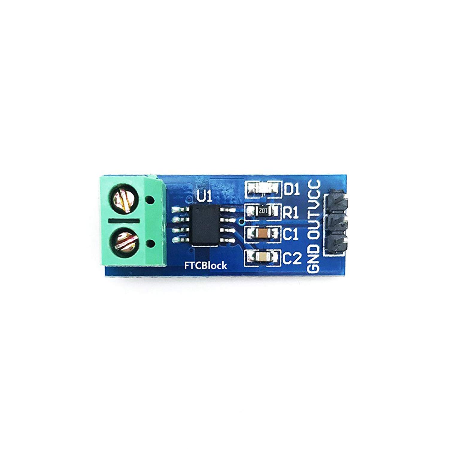
FTCBlock 3pcs Current Sensor ACS712 20A Range Analogue AC/DC for Arduino Ras PI
Southern Tech
- Current sensor chip: ACS712ELC-20A
- Pin 5V power supply, on-board power indicator
- The module can measure the positive and negative 20 amps, corresponding to the analog output 100mV / A
- There is no the detection current through, the output voltage is VCC / 2
- The PCB board size: 31 (mm) x13 (mm)
User questions & answers
| Question: | Max input voltage 30A |
| Answer: | See this link for the full spec of the hall current sensor: https://www.sparkfun.com/datasheets/BreakoutBoards/0712.pdf Isolation is > 2KV, the current capacity is 30A |
| Question: | Does this have an adjustable current out at which it trips a logic level? If not do u kno of a device that does |
| Answer: | This device is a sensor that measures current and outputs mV in proportion to the current it is sensing. You would have to use this sensor to feed the logic to perform the function you want to trip. For example, this device would feed a microcontroller program ( using the devices library) then the program provides the logic to trip an external device. |
Product features
Product Features
- The Current Sensor ACS712 provides economical and precise solutions for AC or DC current sensing in industrial, commercial, and communications systems.
- Typical applications include motor control, load detection and management, switched-mode power supplies, and overcurrent fault protection.
Technical Specification
Total output error 1.5% at TA = 25°C
Sensor IC Allegro ACS712ELC-xxB-T
Internal conductor resistance 1.2 mΩ
Power operation 5V
Temperature -40°C to 85°C
Output Signal Analog

Battery Monitor, DROK Voltage Meter Ammeter DC 0-300V 200A STN Digital LCD Display Tester, Voltmeter Multimeter Solar System Setup Power Energy Capacity Volt Current Detector Panel with Hall Sensor
Product description
DROK Battery Tester Digital Voltage Ampere Power Energy Multimeter
Technical Parameters:
Model: WLS-PVA200
Current measuring range: 200A
Current resolution: 0.2A
Power supply range: DC5~90V
Voltage measuring range: DC0~300V
Voltage resolution: 0.1V
Capacity measuring range: 0~999AH
Power measuring range: 0~999KW
Electric energy measuring range: 0~999KWH
Measurement error:±1%
Refreshing speed: 0.5S/time
Installing size: 76.0mm * 39.5mm
Diameter of transformer:Φ20mm
Working current: backlight on: 10MA;backlight off:4MA
Package includes:
1 X LCD Digital Cullen Meter
- Multifunctional Meter: DROK multimeter panel is available to measure percentage and AH of remaining capacity, DC positive and negative bidirectional current, DC voltage, DC positive and negative power, DC positive and negative bidirectional accumulated electric energy. Voltage measurement range is DC 0-300V, current measurement range is 0-200A.
- Hall Sensor & Easy Mount: the voltage amperage meter is coming with a Hall transformer to for isolated measurement, reliable and safe; accepting two-wire system connection and three-wire system connection, could be powered DC5~90V, easy and simple to wire this meter up.
- Display: backlight can be controlled to be ON or OFF as user’s need; Equipped with full angle of view LCD screen, users could see the display clearly whenever at night and day, indoor or outside, even under the sunshine.
- Alarming Function: it will alarm and flash to draw your attention when the real voltage is higher or lower than preset alarming voltage and real current is higher than preset current; It will also alarm and flash to remind you to charge for your device when the remaining capacity of battery is low.
- Wide Applications: Can be used as dc amp meter, digital volt meter, power meter, battery capacity monitor. Suitable for all kinds of batteries, such as Lead-acid batteries, Lithium Polymer batteries, lithium iron phosphate batteries and etc. With function of storing date when power down, using this meter, no need to worry that your electric data will be lost.
User questions & answers
| Question: | what is the actual size of the product? lxwxh .. nothing listed here |
| Answer: | Inside measurements for the cut out are 72mm wide, 39mm tall and 25mm deep. The outer face plate is 7mm wider and 3mm taller, not much difference. I made a matting skirt out of thin black plastic since it's very difficult to cut a perfectly sized rectangle in the wall. |
| Question: | How to use menu options no user manual is included |
| Answer: | Dear customer, We have pdf manual on product deatils page. It can be found on the "Technical Specification" from this page. Or please click on this link directly. https://m.media-amazon.com/images/I/B1ubSSVdpyS.pdf Best regards, DROK |
| Question: | specs say it is a 200A meter, yet some say its only goes up to 100A, can anyone confirm this can measure up to 200A |
| Answer: | im sitting looking right at one 6months installed ... it regularly measures 155 amps of 12volt charge and up to 199amps discharge .... those are my system limits witb a 5000w inverter several golf cart batteries and two 100amp chargers |
| Question: | How long i as the cable for sensor and what is max wire size that will fit in sensor |
| Answer: | The sensor cable is about 8 inches long but i cut my cable and extended it to about 10 ft. I testes it up to 15ft and it worked fine. You could possibly go longer. Just use a good quality multi wire cable, or make your own. About 18AWG probably OK. I recall the hole as 20mm, roughly 3/4 inch diameter. No problem for RV battery cable. Remember you can run more than one wire through the hole, That way you can still use battery terminal as the tie point for the various wires that may already be connected there. The sensor will read the Sum of currents, that is for example, if you have charging from a solar system at say 5A, and a discharge load to lighting at say 3A, your meter will show 2A charging. Hope this helps |
Product features
Buttons
With 2 buttons to be easily operated.
Bi-direction Current
With the capability to measure current in forward and reverse direction.
Backlight Control
Backlight can be manually turned on/off via the button.
Can be clearly viewed in any light conditions.
Latest Reviews
View all
Samsung Tv Led Tvs
- Updated: 25.01.2023
- Read reviews

Bunn Coffee Maker Mades
- Updated: 15.03.2023
- Read reviews

Electric Weed Eater
- Updated: 26.01.2023
- Read reviews

Bead Charms For Pandora Trolls
- Updated: 23.03.2023
- Read reviews

Mcafee Mac Internet Security Softwares
- Updated: 15.03.2023
- Read reviews