14 best buck converters
A buck converter, also known as a step-down converter, is a type of power electronic circuit used in electronics and power supply systems to efficiently reduce the voltage of a DC power source. It is a fundamental component in various applications, including battery chargers, voltage regulators, and power management systems.
Here are some key points about buck converters:
Voltage Reduction: The primary function of a buck converter is to reduce the input voltage to a lower output voltage level. It is commonly used to step down voltage levels from a higher source voltage to a lower voltage required for electronic components or devices.
Efficiency: Buck converters are known for their high efficiency. They achieve this efficiency by rapidly switching the input voltage on and off using a semiconductor switch (typically a transistor) and then smoothing the output using an inductor and a capacitor. This switching action minimizes energy loss as heat.
PWM Control: Pulse-width modulation (PWM) is often used to control the duty cycle of the switching transistor in a buck converter. By adjusting the duty cycle, the output voltage can be regulated precisely.
Continuous vs. Discontinuous Mode: Buck converters can operate in continuous or discontinuous mode depending on the load conditions. In continuous mode, the inductor current never reaches zero during the switching cycle, while in discontinuous mode, it does. The choice between these modes depends on the specific application and load requirements.
Applications: Buck converters are used in various applications where voltage reduction is required, such as powering microcontrollers, charging batteries, and providing a stable voltage to integrated circuits in electronic devices.
Voltage Regulation: They provide good voltage regulation, helping to maintain a stable output voltage even when the input voltage or load conditions change.
Protection Features: Some buck converters include protection features like over-current protection, over-voltage protection, and thermal shutdown to ensure the safety and longevity of the circuit.
Efficiency vs. Voltage Drop: While buck converters are highly efficient, it's essential to consider that there is some voltage drop across the circuit. This drop is typically small but should be taken into account when designing power systems.
In summary, buck converters are a crucial component in electronics and power supply systems, allowing for efficient voltage reduction and voltage regulation.They are widely used in various applications to provide a stable and regulated power source for electronic devices and circuits.
Below you can find our editor's choice of the best buck converters on the market
Zixtec 10 Pack LM2596 DC-DC Buck Converter Step Down Module Power Supply DIP Output 1.25V-30V 3A (ZT001)
Product description
Electrical Parameters:Input: DC 3.2V to 35V (input voltage must be more than the output voltage can not be higher than boost 1.25v.)Output: 1.25V to 30V DC voltage is continuously adjustable, high efficiency and maximum output current of 3A.Features: All solid capacitors using SANYO, 36u thick circuit boards, high-Q inductors with high power output LED indicatorSize: 45 21 13mm / 1.69 0.83 0.51inch (including potentiometers)minimum with locating hole with LED indicator DC-DCInstructions:Access to power (3-35V), adjust the blue potentiometer knob (clockwise rotation generally boost, buck counterclockwise rotation) and with a multimeter to monitor the output voltage reaches the required voltage.Wiring:1. welding, welded directly to the power line input (output) port;2. solder pins, or pins can be inserted through the lead insertion use in tunnel plate; soldered directly to the PCB after another or add pins.Note: The input and output can not be reversed, reverse might burn chips;This is a step-down module, the input voltage is higher than the required output voltage;Output 2A or less long period of time without additional heat sink output current is greater than 2.5A (or output power greater than 10W) to work long hours please add heat sink.Package Included: 10pcs X LM2596S Module
- Input voltage range: DC 3.2V to 35V (input voltage must be higher than the voltage output to 1.5V or more can not be boosted.)
- Output: 1.25V to 30V DC voltage is continuously adjustable, high efficiency and maximum output current of 3A.
- All solid capacitors using SANYO
- 36u thick circuit boards
- High-Q inductors with high power output LED indicator
User questions & answers
| Question: | where should I add a heat sink |
| Answer: | Not really a need for a heat sink in most applications. They're rated for 3A but that is pushing it for continuous use. Best spot would be the MOSFET for a heatsink. |
| Question: | Is it possible to combine output from multiple modules to supply current over 3 Amps |
| Answer: | into a common capacitor, common ground with a decent quality power diode out of each + on the converter to the cap (remember the .6-.7 V drop). Don't push the limits. For better isolation a small local cap on each converter output before the feed diode. And in a perfect world a power resistor to limit current draw on any one converter (obviously small ohmage and moderate power capacity as its pure parasitic when all is working properly). Depending on the load, perhaps a 47 - 100 uf cap common and a 1uf local. No promises or guarantees here. And notice that the small variance in the output settings will mean that the high voltage output will do most of the work (which is where the resistor and local cap help). |
| Question: | I don't understand the limitations. Can it be used to bring 5V down to 3V |
| Answer: | It absolutely can. I have used these to convert my 12V supply into both 5V and 3.3V |
| Question: | At 12 volts input and (say) 5 volts output, what is the quiescent (no-load) current on the 12 volt side? Thanks |
| Answer: | On my regulators the no load input current for 12V in 5V out is 7.8 mA with the output indicator LED installed. With the LED, the no-load current depends strongly on output voltage rising to 23 mA at 11V output. With the LED removed the no load input current at 12 V in 5 V out is 6.0 mA. Without the LED is independent of output voltage. |

6 Pcs ) MCIGICM LM2596 Buck Converter, DC to DC 3.0-40V to 1.5-35V Step Down Power Supply High Efficiency Voltage Regulator Module
Product description
MCIGICM LM2596 DC-DC Step-Down Buck Converter Power Module
Features:
Module property:Non-isolation buck
Rectification mode:Non-synchronous rectifier
Input voltage:3V-40V
Input Current: 2A Output voltage:1.3V-35V
Output current:Rated current is 2A,maximum 3A(Additional heatsink is required)
Conversion efficiency:92%( highest )
Switching frequency:65KHz
Output ripple:30mV( maximum )
Load regulation:±0.5%
Voltage regulation:± 2.5%
Work temperature:-Minus 40 degrees - 85 degrees
Dimension:43mm*21mm*14mm(L*W*G)
Package:
6 * Lm2596 dc-dc buck converter step down module
- Input: DC 3 V to 40 V. Current: 2A **NOTE** Input voltage must be 1.5 V higher than the output voltage, no boost.
- Output: DC 1.5 V to 35 V. Output current: 2A ( Max).
- All products are tested for stability, consistency and reliability. Ensure product excellence.
- Steps: turn the screws before you apply voltage, then connect to power source, adjust the swirl button on the blue potentiometer and monitor voltage with multimeter to get the needed voltage (The factory have tested these at max voltage so they are very high by default, takes about 15-20 turns CCW before the voltage starts ramping down)
User questions & answers
| Question: | What is the max power rating in watts? it says 2 -3 amps, but not a voltage. i can run 35 volts at 2 amps? that's 70 watts |
| Answer: | Output: DC 1.5 V to 35 V. Output current: 2A (3A Max with heatsink ). Using this information the simple assumption would be 3 Watts (4.5 Watts Max) @ adjusted 1.5V Output scaling to 70 Watts (105 Watts Max) @ adjusted 35V. That is just basic theory. |
| Question: | Are the input output pins spaced to fit on a breadboard |
| Answer: | The pins are on the extreme corners. I soldered a pin to each and it did fit. Remember to turn the pot all the way, or it seems as if the part is no good. All six of mine work. |
| Question: | Will this product work to convert -20 vdc to -12 vdc |
| Answer: | Can't guarantee anything but if you connect the negative voltage to the ground terminal and the ground of your negative supply to the positive terminal it should work. Just make sure you isolate the unit completely and be careful of power dissipation in the unit. Your positive output terminal will be ground and your negative or ground terminal will be your negative voltage at the output. |
| Question: | Does it have under-voltage protection? Will it burn up if the voltage powering it drops below the voltage you set it at? Or will it simply turn off |
| Answer: | If you exceed the capacity of the diodes, yes. |

eBoot Mini MP1584EN DC-DC Buck Converter Adjustable Power Supply Module 24V to 12V 9V 5V 3V (6 Pack)
EBOOT
Product description
eBoot Mini MP1584EN DC to DC buck converter adjustable power supply module 24V to 12V 9V 5V 3V, 6 Pack
Specifications:
Input voltage: 4.5 V to 28 V
Output voltage: 0.8 V to 20 V
Output current: 3 A (maximum)
Conversion efficiency: 92% (maximum)
Output ripple: less than 30 mV
Switching frequency: 1.5 MHz (highest), typically 1 MHz
Operating temperature: -45 ℃ to 85 ℃
Size: 22 mm by 17 mm by 4 mm
Application: DIY mobile power, monitor power supply, power buggies, camera power supply, car power, communications equipment supply,etc.
Package includes:
6 x Mini MP1584EN DC to DC buck converter
You can adjust the voltage by placing a multi-meter on the output, synchronously, using a screw driver to adjust a potentiometer. It can be minute adjustments to achieve a precise voltage.
Kindly reminder
These boards are adjustable current limiting, fixed 3A current limit.
Please make sure that this module within its working range before using.
Please don't output short circuit, otherwise the board would burn out.
When setting the parameter, please make sure output voltage is stable before using the module to avoid any possible damage.
Tips:
Please check if the product package is intact before opening.
Please check if the negative and positive terminals are accessed correctly before operating.
The input voltage should not be over 28 V to avoid damage.
- Mini MP1584EN DC to DC buck converter module with a wide operating range
- Input voltage: 4.5 V to 28 V; Output voltage: 0.8 V to 20 V
- Output current: 3 A (maximum); Conversion efficiency: 92% (maximum)
- Output ripple: less than 30 mV; Switching frequency: 1.5 MHz (highest), typically 1 MHz
- Operating temperature: -45 ℃ to 85 ℃; Size: 22 mm by 17 mm by 4 mm; Warning: do not reverse the positive and negative terminals to avoid any possible damage; Do not use light load (less than 10% of output power) or without load
User questions & answers
| Question: | Does it get very hot to touch when working as a 12V to 5V converter |
| Answer: | It’s a switcher dc to dc converter. So it doesn’t get hot like a linear converter. I did a short 3 amp test and it didn’t get hot. I use these between 60mA to 700mA without it getting warm at all. |
| Question: | I'm trying to go 12v to 5, I configure for 5v no load, why do I get 1.8v with load |
| Answer: | If you are putting out 5v with nothing attached, then you attach a device that draws 3.2 v, what is left over to read is only going to be 1.8 v. if you are still wanting 5v after you attach the load, you will need to increase the output to 8.2 v. |
| Question: | Is the outout regulated? After it is set will hold the output voltage even if the input voltage varies |
| Answer: | I've had very good success with these inexpensive little guys, using as many as three in one control box, that runs one 24 V DC motor, one 12 V DC motor. Each motor is controlled by its own tiny Adafruit trinket microcontroller with one of those requiring 5.5 VDC logic level, and the other requiring 3.3 VDC logic power. I only bring 24 VDC into the box and use the first Buck converter just step down to 12 VDC, at that point I have the correction power for both motors. From the output side of the first Buck converter, I use a second one to step down to 5.5 VDC, and a third one to step down to 3.3 VDC, which satisfies the needs of both microcontrollers. The potentiometer provided on the Buck converters, seems to be less than one turn from high to low, so adjusting them is very touchy, but you get used to it. You must have a minimum of one volt higher input voltage, than you want to get on your output voltage. If you input 9 VDC you can output anything from 3 to 8, but not 8.5 for example. If you need 8.5, your input voltage would have to be at least 9.5, and so on. In my experiments, I could carefully dial one in to output 3.3 VDC, which I use for my most sensitive microcontroller, and after that, I could switch my input to 6, 9, 12, and 24 VDC with no measurable change to the output of 3.3 VDC without making any further adjustments to the Buck converter. I'm pretty impressed, and have reordered a couple times. I hope that answers your question. |
| Question: | Can someone please explain this in the bullet points: "Do not use light load (less than 10% of output power) or without load". Will it fail |
| Answer: | The comments about this minimum load does not make any sense to me. I have been reading the chip specs (https://www.monolithicpower.com/pub/media/document/MP1584_r1.0.pdf) and see no load operation consuming 125uA. I also see special features "High-Efficiency Pulse Skipping Mode for Light Load" for the chip. Nowhere in the documentation does it specify a minimum 10% of full requirement. I understand without load that it may not regulate properly and the voltage could climb up to input voltage. That part makes sense. However, the 10% makes no sense to me. Nothing in the documentation mentions this. I ordered these and will be testing, but if it really does require a min 10% load then it won't be usable for my application. At 9 volts that is 2.7W. That is a big resistor to maintain the min load. |
D-PLANET [4-PACK] 5A DC-DC Adjustable Buck Converter 4~38v to 1.25-36v Step Down Power Supply High Efficiency Voltage Regulator Module
Product description
Product Features
This product is a 180 KHz fixed frequency PWM buck (step-down) DC/DC module,capable of driving a 5A load with high efficiency, low ripple and excellent line and load regulation.
Parameters:
Input Voltage: DC 4-38V, error ±0.1V
Output Voltage: DC 1.25V to 36V
Output Current: 5A(MAX) It is recommended to use under 4.5A (NOTE: When using high power, add a heat sink to the power supply chip)
Size: 5.4x2.3x1.8CM
Weight: 16g
Fuction:
1.Built in over-temperature protection function
2.Built in current limit function
3.Built in output short-circuit protection function
How to use
1.Access the power supply (4-38V), the power indicator light, the module is working properly.
2.Adjust the blue potentiometer knob (usually clockwise rotation boost, counterclockwise rotationStep-down) and monitor the output voltage with a multimeter to reach the required voltage.
3.A customer reflects the module output voltage can not be adjusted, always equal to the input voltage. When you encounter this problem, please first counterclockwise rotation potentiometer 10 laps above, and then use the module can be normal adjustment of the voltage.
- Input voltage range:4~38V (Note:input voltage not over 38V)
- Output voltage range:1.25-36VDC adjustable.Output current: 0-5A,Output power: 75W
- High conversion efficiency up to 96%
- Updated Version: updated from LM2596 and better than it, with reverse voltage protection, over-temperature and short-circuit protection, thus making it much safer to use
- 100% SATISFICATION SERVICE: If there are any problem with our products, please feel free to contact us. you can request a refund for any single module and no need to return it.; Any problems you can contact us and we will try our best to resolve it till you satisfied.
User questions & answers
| Question: | if i have a 12v input why am i only getting 2 volts no matter if i turn it clockwise or counter clock wise ?? what am i doing wrong |
| Answer: | Assuming that you did not get a defective board (Try another one?), you must turn the potentiometer MULTIPLE times. If memory serves me correctly, you turn the pot clockwise to increase the voltage. |
| Question: | volts but the highest output is 3.21 volts. i have run the pot full ccw to <1 volt, then full cw to max output. is there a min amp required |
| Answer: | I'm running 12V into mine and was able to dial it in to 5.00V with no load. So no, there shouldn't be any minimum current for stable voltage. Yours might be faulty. |
| Question: | what is the max Amp input? Will it work with 12V 10A input |
| Answer: | I'm a mechanical and not electrical engineer but based on my understanding and assuming you're talking about the step DOWN converter - your question doesn't quite make sense. 12 Volt input is obviously fine according to the spec. Based on your set output voltage, and what you have hooked up on the output end, it will draw a set amount of current. So the current it's drawing on the output will determine (and be the same as) what's being drawn through the input. It shouldn't be drawing more than 5A max of current or it's likely to fry the board. |
| Question: | what value is the potentiometer? I would like to use a different style one |
| Answer: | The ones on mine are 10-turn 50K ohm. I think as long as the 5k or higher it will just perform a voltage divider and be fine, it just burns more current at 5k than 20k or 50k... Figure 30v regulated output will be 0.6mA on 50k or 6mA on 5k. |
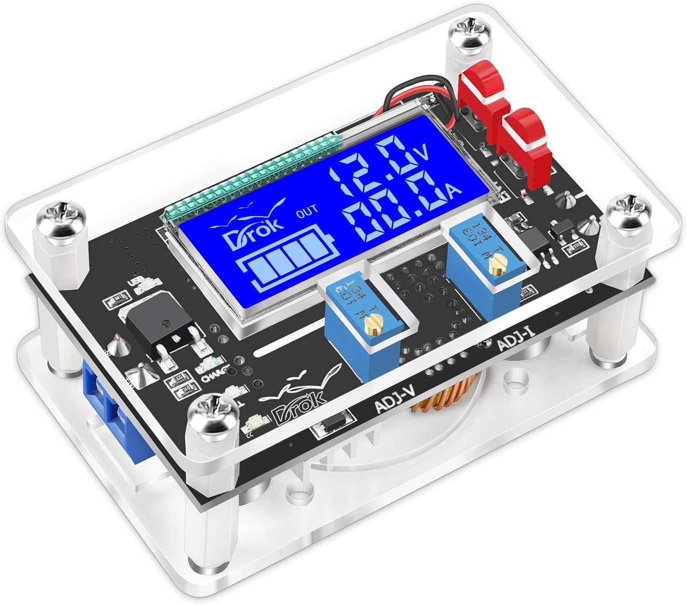
DC Buck Module, DROK Adjustable Buck Converter Step Down Voltage Regulator 6V-32V 30V 24V 12V to 1.5-32V 5V 5A LCD Power Supply Volt Reducer Transformer Module Board with USB Port Protective Case
- PARAMETER --- input voltage range DC 6V-32V; output voltage DC 1.5V-32V; max output current 5A, recommend use of within 4.5A; max output power 75W, recommend use of within 50W.
- GENERAL USE --- as ordinary step-down module with over-current protection; as constant current LED driver module; DIY a solar power controller, etc.
- DISPLAY --- large clear digital LCD display voltage & current value simultaneously.
- FEATURE --- constant current/voltage mode; voltage calibration & current calibration; USB interface; protective case; short-circuit protection; over-temperature protection; input reverse connection protection.
- NOTE --- 1). Output voltage is set as around 20V by default, if your input is lower than that, please turn potentiometer anticlockwise for 10 laps or more until voltage changes. 2). The case is packaged unassembled to avoid damage during transit. It needs to be manually installed. 3). Please carefully read the user’s manual, especially the “Cautions” before using. You can find the PDF Instructions on this page -- Product information -- Technical Specification -- User Manual [PDF].
User questions & answers
| Question: | In the instructions it says to use a diode if using for charging, where does the diode go |
| Answer: | I don't know what application you are talking about, or which instructions your are talking about, but the right diode in between the power supply and the 'in' on the DROK would not hurt. It probably would be a good thing to have one on the 'out' line as well. A diode is a electric check valve that keeps the power going one way, and will the power to reverse and go backwards. I have solar panels, and they each have a diode right in the box on the back of the solar panel. The power comes from the panel, through the diode, to my DROK adjustable converter, 'IN' the DROK - where it is adjusted - 'OUT' the DROK - to the battery it is charging. This makes the DROK a monitor/regulator. If you have any other questions, let me know, describe your application, (power source, and where the power is to be used) You can also use the DROK as a super light dimmer control, or to control the speed of any small motor. |
| Question: | I need a cheap driver for an 18v, 42w led light. Has anyone used this with a similar or higher output and does it work well at that high an output |
| Answer: | Yes it should. I haven't used it for an 18v LED but I have used it for multiple 12v LEDs and even a couple 15m 12v LED Strips. It perform quite well. I have used it at 36v for charging my Xiaomi Mijia M365 electric kick scooter for a short period also. The only issue I have come across are the little red button pieces, they tend to slide off the momentary button on the circuit board and become kinda lodged under the plastic case. But I wouldn't hold that against purchasing this item since the functionality isn't degraded because of that. |
| Question: | Delivered without instructions -- where can a 'user's manual' be found |
| Answer: | Hi, there is a PDF Instructions on the product page -- Product information -- Technical Specification -- User Manual pdf https://images-na.ssl-images-amazon.com/images/I/C1X8DiomGTS.pdf Hope it could help you. |
| Question: | Is the usb output fixed or is it adjustable |
| Answer: | It's not fixed. I had it as high as 13.3 volts in my application of the USB connector. You need to set output to 5v before using any standard usb device. |
| Question: | Are these marked with model numbers? I would hate to get these and have no clue of each one's model numbers once out of box |
| Answer: | yes they are , and if you look up number it will give you voltage and current characteristics for the model number |
Product features
F-0 Mode
Display output voltage.
F-1 Mode
Display input voltage.
F-2 Mode
Alternately display output voltage & input voltage.
USB Mode
Display USB output voltage.
Turn on/off USB output.

[2 Pack] DC-DC 5A Buck Converter 4-38V to 1.25-36V Step Down Voltage Regulator High Power Module with LED Display
Product description
Features:
- High power DC-DC step down module
- Thickened circuit boards
- Advanced solid-state capacitor
- Short circuit and over-temperature protection
- 100% tested, sealed in anti-static packaging
Kindly Note:
1. Input voltage must be 1.5 V higher than the output voltage, no boost
2. Do not reverse the input and output interface
3. Keep output under 5A (or 75W), and use a heat sink when for a long time working
How to Calibrate the Digital Tube Voltmeter
(Optional steps for the person who need a highly accurate voltage value)
1. Short press the left "ON/OFF" button to start up the digital tube voltmeter. Long press(>1s, <4 seconds) the left button to shut down the digital tube voltmeter.
2. Long press(>4 seconds) the left button to enter self-calibration of voltage measurement(calibration range: -0.5-0.5V, factory setting is 0.0).
"IN" indicator lights = input voltage measurement calibration starts. Then, long press(>2 seconds) the right "Mode" button, "OUT" indicator lights = output voltage measurement calibration starts.
Tap the left / right button to reduce / rise by one unit (since the voltage value of one unit is less than 0.1V, you need to 1-5 times tap the button continuously, so that the voltmeter can change by 0.1V)
3. After calibration, long press(>2 seconds) the right "Mode" button to preserve the adjusted value(no loss with outage) and back to normal voltage display.
Specifications:
- Model: Xl4015E / Digital Tube Voltmeter
- Input Voltage: DC 4V - 38V
- Output Voltage: DC 1.25V - 36V (adjustable)
- Output Current: 0-5A ( recommended working current < 4.5A)
- Conversion Efficiency: 96% (max.)
- Switching Frequency : 180KHz
- Operating Temperature: -45℃ to +85℃
- Size(L x W x H): 62*38*14mm
- Weight: 32g
Package List:
2x DC-DC buck converter module with LED display
8x Copper cylinder / screw nut
2x Heat sink
- 【High Precision】The buck converter consists of 36u thickened circuit boards, high-Q inductance with output LED indicator, and superior solid-state capacitors that can effectively filter out high frequency noise. Suitable for various electronic projects.
- 【Input Voltage】DC 4V to 38V (input voltage must be 1.5V higher than the output voltage, no boost).
- 【Output Voltage】DC 1.25V to 36V voltage is continuously adjustable, maximum output current is 5A.
- 【Mini Size】62*38*14 mm (with potentiometer). 2 sets included.
- 【Easy to DIY】Connect to power source, using a mini screwdriver to increase or decrease output voltage by adjusting the screw on the blue potentiometer and monitor voltage with multimeter to get the needed voltage, clockwise to step up voltage and counterclockwise to step down voltage. (Factory default stays a high voltage, you need to contrarotate about 7-15 circles before the voltage starts ramping down, 1 circle means +/- 1V)
User questions & answers
| Question: | What are the mechanical dimensions of the mounting holes? Center to center and diameter of holes? Thanks |
| Answer: | 2.125 X 1.25. Or 53 X 31 mm. Hole diameter clearance for a 3 mm bolt |
| Question: | Is there a way to reset the chip? I manually self-calibrated it to output 5v but it's outputing 12v. Turning the knob doesn't work anymore either |
| Answer: | Hi, can you please have a try: remove input voltage then re-apply input voltage, and turn potiantiometer counter clockwise a lot of turns ( >10 ) to set resistance to 0 ohms, before the output voltage begins to change. Note: the function of calibration is used to calibrate the display accuracy of voltage, not to adjust the output voltage value. |
| Question: | Won't the tape on the bottom of the heat sink melt when it's gets warm during use |
| Answer: | no, it won't. The tape is a kind of solid gum that can tolerate a certain high temperature ( |

DZS Elec 2pcs DC-DC 5A 4-38V to 1.25-36V Step-Down Regulator Module 12V/24V/36V to 3.3V/5V/12V/24V Large Power Voltage Regulator Buck Converter
Product description
Feature:
Name: DC-DC 5A Large Current Step-Down Power Module
Type: Non-isolated step-down module
Input Voltage: 4-38V (Do not exceed 38V)
Output Voltage: 1.25-36V (continuously adjustable, input must be above 2V higher than output)
Input Current: 0-5A (Suggest to use under 4.5A for long time work)
Output Power: 75W (Max) Please strengthen the cooling when the output is above 50W.
Working Temperature: - 40 degree to + 85 degree
Working Frequency: 180KHz
Transfer Efficiency: 96% (Max), relate to input voltage, output voltage, current, dropout voltage.
Load Regulation: S(I) less than or equal to 0.8%
Voltage Regulation: S(u) less than or equal to 0.8%
Power Light: Yes
Over Temperature Protection: Yes, Automatically shut off output once over temperature.
Reverse Voltage Protection: NO (If need, please add large current tube.)
Shore Circuit Protection: NO
Installation: 2x3mm Screws
Connection Mode: Soldering, V-IN for input, V-OUT for output
Size: 54x23x15mm
This module can be applied to step-down applications that input voltage is higher than output voltage, such as store battery, power transformer, DIY adjustable regulated power supply, 24V vehicle laptop power supply, commercial unit voltage reduction, 12V to 3.3V, 12V to 5V, 24V to 5V, 24V to 12V, 36V to 24V and so on.
Note:
1. This module is only for voltage reduction, there is no the function of constant current and current limiting, can be transferred to 5V to connect mobile etc. other device, but can not be used for the products with small internal resistance.
2. Factory testing defaults values is input 24V, output 18V, if there is no response to adjust voltage, please contrarotate the potentionmeter many circles.
Package Include:
2pcs 5A 4-38V Step-Down Buck Converter Module
- Input Voltage: 4-38V (Do not exceed 38V); Output Voltage: 1.25-36V (continuously adjustable, input must be above 2V higher than output)
- Input Current: 0-5A (Suggest to use under 4.5A for long time work); Output Power: 75W (Max) Please strengthen the cooling when the output is above 50W.
- Working Temperature: - 40 degree to + 85 degree, with power light, over temperature protection, but there is no reverse voltage protection.
- Small size, large power, high transfer efficiency, up to 96%.
- This module can be applied to store battery, power transformer, DIY adjustable regulated power supply, 24V vehicle laptop power supply, commercial unit voltage reduction, 12V to 3.3V, 12V to 5V, 24V to 5V, 24V to 12V, 36V to 24V and so on.

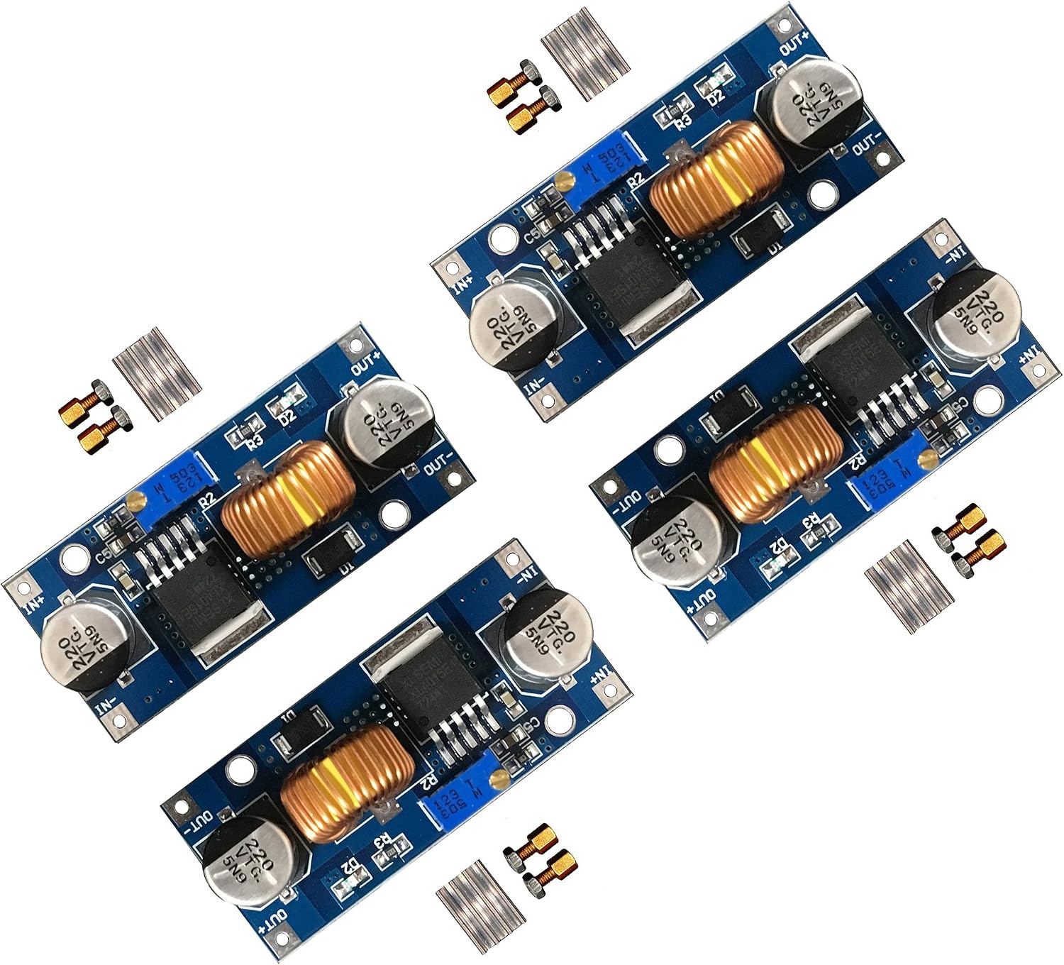
4 Pieces Adjustable LM2596S DC-DC Buck Converter Reduced Voltage Regulator Power Module 36V 24V 12V to 5V 2A Voltage Stabilizer with Digital Voltmeter Display
Product description
Features:
How to use:
1. Press the button in a short time (1 second) so that "in" LED lighted, the voltmeter shows the value of input voltage.
2. Press the button in a short time (1 second) again so that "out" LED lighted, the voltmeter shows the value of output voltage.
3. Rotate the top screw of potentiometer clockwise to boost the value of the output voltage, anti-clockwise to reduce it.
4. Long press the button between 1 and 4 seconds to turn off the voltmeter.
How to adjust accuracy of input/output voltage:
(for the person who need a highly accurate value of number)
1. Long press the button for more than 4 seconds, then release, voltmeter and "in" LED flash in synchronization entering into the input voltage calibration mode.
2. Press the button in a short time (1 second) to adjust the value (range from -0.5 - 0.5V), positive means to rises units, negative means to minus units. (Due to a unit is less than 0.1V, so you have to continuously press 1 to 5 times to see the voltmeter change 0.1V).
3. Long press the button for more than 2 seconds and then release to enter the output voltage calibration mode.
4. After calibration, long press the button for more than 2 seconds all parameters will be saved automatically and back to the voltage display.
Specification:
Function:
Built in over-temperature protection function
Built in current limit function
Built in output short-circuit protection function
Size: approx. 6.6 x 3.9 x 1.8 cm/ 2.6 x 1.5 x 0.7 inches
Package include:
4 x LM2596s buck converter DC to DC
Note:
Please keep away from little kids.
- Product parameters: input voltage is 4.0V - 40V, output voltage is 1.25V - 37V, output current is 2A (normal and stable) and 3A max, conversion efficiency 92% (highest), output ripple under 30mV, switching frequency 150KHz, operating temperature is -45 to 85 degree Celsius
- Simple to operate: the voltmeter can be turned off, and the switch can be turned off by pressing and holding the switch for more than 1 second and less than 4 seconds, once the voltmeter is turned off, simply press the switch to turn on the voltmeter
- Easy to use: with terminal block, no soldering iron is also convenient to use, and retain the wire bond point (the input voltage must be higher than the voltage to be output by 1v or more)
- Output current: the maximum output current can be as high as 3A, the recommended working current is about 2A, more than 2A plus heat sink
- Nice design: with 150KHz internal oscillation frequency, features low power consumption and high efficiency; When the output voltage cannot be adjusted and is always equal to the input voltage, please turn the potentiometer counterclockwise for more than 10 turns, and then use the module to adjust the voltage normally; This is because when the module leaves the factory, the default output voltage is about 20V
User questions & answers
| Question: | Does it work |
| Answer: | The converter works well,four-piece converter is very affordable |
| Question: | Can this be used to step down from 9v to 5v |
| Answer: | Yes, input voltage is 4V - 40V, output voltage is 1.25V - 37V. |

D-PLANET [8-Pack] LM2596 DC-DC Adjustable Buck Converter 3-40 V to 1.5-35v Step Down Power Supply High Efficiency Voltage Regulator Module …
Product description
Product Features
Parameters:
Input Voltage: DC 3 -40 V
Output Voltage: DC 1.5 - 35 V
Output Current: 3A(MAX) It is recommended to use under 2A (NOTE: When using high power, add a heat sink to the power supply chip)
Load adjust ratio: +/-0.5%
Voltage adjust ratio: +/-2.5%
Transferring efficiency: 92% Max(the higher output voltage, the higher efficiency)
ON/OFF frequency: 150KHz
Output ripple: 200mV
Module feature: buck and non-isolated
Rectification method: non-synchronous rectification
Size: 5.4x2.3x1.8CM
Weight: 16g
Fuction:
1.Built in over-temperature protection function
2.Built in current limit function
3.Built in output short-circuit protection function
How to use
1.Access the power supply ( 3 -40 V), the power indicator light, the module is working properly.
2.Adjust the blue potentiometer knob (usually clockwise rotation boost, counterclockwise rotation Step-down) and monitor the output voltage with a multimeter to reach the required voltage.
3.A customer reflects the module output voltage can not be adjusted, always equal to the input voltage. When you encounter this problem, please first counterclockwise rotation potentiometer 10 laps above, and then use the module can be normal adjustment of the voltage.
Package includes:
8X LM2596 board
8 pieces of heat sink
- Input voltage range: DC 3 -40 V (input voltage must be 1.5 V higher than the output voltage, no boost)
- Output voltage range:Output: DC 1.5 - 35 V voltage is continuously adjustable, maximum output current is 3 A
- 8 pieces of LM2596 board and heat sinks included
- Easy to make it work and convenient to accurately adjust the output voltage with a mini screwdriver.
- 100% SATISFICATION SERVICE: If there are any problem with our products, please feel free to contact us. you can request a refund for any single module and no need to return it.; Any problems you can contact us and we will try our best to resolve it till you satisfied.(Note:The factory have tested these at max voltage so they are very high by default, takes about 15-20 turns CCW before the voltage starts ramping down)
User questions & answers
| Question: | Will they mount on a .1" pitch breadboard / prototyping board |
| Answer: | There are all sorts of ways to mounting it on any size board. Just have to figure in heat displacement for your project. |
| Question: | can somebody give me accurate size of the board in inches or mm? Thank you |
| Answer: | The board is about 30mm by 15 cm |
| Question: | What is the limit on input current? If I have a 24v 2 amp supply going to 5v, will this break the converter |
| Answer: | Simple answer: A 24VDC power supply that can deliver 2A is well within spec for this module, so no, that won't break it. These converters can handle DC Voltages up to 30V, and current up to 3A (with heat sink properly installed). The recomnended max continuous current is 2A with the heat sink. Remember that current is "pulled" through a circuit by the devices being powered, not "pushed" by the DC power supply. You So make sure that the total current drawn by any/all devices powered by these are kess than 3A, and you should be OK. 2A or less is even better. If your power supply doesn't have a fuse or circuit breaker for over-current protection, you may want to add one one before this module. |
| Question: | Do these have polarity input protection |
| Answer: | To answer your question, I connected one with reverse polarity. It has some measure of protection evidenced by the fact that the unit still worked when re-connected with proper polarity. That said, all you need to do to add the protection is put a simple diode (Schottky Diode is best) in series with this unit's +input. Doing that will not affect this unit's operation. Just about any 1 to 2 AMP diode will work for this. You don't have to use a "Schottky" but it's considered best because of its low internal voltage drop. In your application, it is of no consequence. - Bill |

8 Pack Ultra Small MP1584EN DC-DC Buck Converter 3A Power Adjustable Module 24V to 12V 9V 5V 3V
Product description
8 Pack ultra small MP1584EN DC-DC buck converter 3A power adjustable module 24V to 12V 9V 5V 3V
Application:
It is suitable for DIY mobile power, monitor power supply, power buggies, camera power supply, car power, communications equipment supply, etc.
Features:
You can adjust the voltage by placing a multi-meter on the output, synchronously, using a screw driver to adjust a potentiometer. It can be minute adjustments to achieve a precise voltage
Kindly reminder:
These boards are adjustable current limiting, fixed 3A current limit.
Please make sure that this module within its working range before using
Please don't output short circuit, otherwise the board would burn out
When setting the parameter, please make sure output voltage is stable before using the module to avoid any possible damage
Use precautions:
Please check if the product package is intact before opening.
Please check if the negative and positive terminals are accessed correctly before operating, do not reverse the positive and negative terminals to avoid any possible damage
The input voltage should not be over 28 V to avoid damage
Do not use light load (less than 10% of output power) or without load
Specifications:
Input voltage: 4.5 V to 28 V
Output voltage: 0.8 V to 20 V
Output current: 1.8 A(typical), 3 A (maximum)
Conversion efficiency: 92% (maximum)
Output ripple: less than 30 mV
Size: 22 mm by 17 mm by 4 mm
Package includes:
8 x Ultra small MP1584EN DC to DC buck converter
- Package include: 8 pack ultra small MP1584EN DC to DC buck converter module with a wide operating range
- Input voltage: 4.5 V to 28 V; Output voltage: 0.8 V to 20 V
- Output current: 1.8 A(typical), 3 A (maximum); Conversion efficiency: 92% (maximum)
- Output ripple: less than 30 mV; Size: 22 mm by 17 mm by 4 mm
- Use precautions: do not reverse the positive and negative terminals to avoid any possible damage; Do not use light load (less than 10% of output power) or without load, please read the product description in detail before using it
User questions & answers
| Question: | I require a stable 5V supply under varying current draw of about 200ma - 800ma. Is the output voltage stable under varying load? thanks |
| Answer: | I am using it to run a 12v depth sounder on a 20v nicad battery. As it runs voltage varies from a volt or so. I believe that is because the device load goes up or down, so I would say no. |
| Question: | Will this take a 12v input and drop it 1.2v for landscape led lighting battery conversion |
| Answer: | Had it down to 1.5v but not sure how stable under load |
| Question: | Can this boost 5V up to 12V |
| Answer: | No Not a boost converter |
| Question: | Dos this carry a common ground or are they seperate |
| Answer: | separate ground connections |

Adjustable Voltage Regulator, DROK DC to DC 5.3V-32V to 1.2V-32V 12V Power Supply Module, 12A LCD Step Down Volt Transformer 160W CC CV Buck Converter Reducer
- DROK power supply module input voltage range is DC 5.3-32V; output voltage range is DC 1.2-32V, can be arbitrary adjustable; output current can be 8A for long term use, if enhance heat dissipation, it can reach 12A; max output power is 120W, if enhance dissipation, it can reach 160W.
- LCD Display: the buck converter is designed with LCD, can display input and output voltage, output current and output power; voltage display resolution is 0.05V, current display resolution is 0.005A.
- Safe Protection: the voltage regulator module is with reverse connection protection at input terminal, reverse connection will not burn; short circuit protection.
- Application: the volt conversion board can be used as an ordinary buck module with over-current protection; used as a high-power LED constant current driver module; DIY a solar power controller, etc.
- Button Control: button control output voltage ON / OFF status, and you can set the default output state is ON or OFF of the next time power-on.
User questions & answers
| Question: | Why the builtin current meter shows in/out currents the same when i am stepping it down from 12v to 5v? hope it didnt waste all (7 x current) watts |
| Answer: | 7 watts is 7 watts current no matter what the voltage is. The “in” current should be the same as the “out” current minus whatever the module uses in the step down process - which is negligible. If you want to limit the current (watts), the other pot will do that. |
| Question: | Can i charge a 12v car battery with this if i have a laptob cord or computer power supply hooked to it |
| Answer: | As long as the laptop power supply can output at least 16 volts. A 12v computer power supply hasn't got enough voltage. A car battery needs approx 14v. You can Google the proper charge voltage for your chemistry. This is buck only so the supply voltage must be higher than the desired output voltage. This power supply has no way of knowing when the battery is fully charged. So be careful what you set the output voltage to so as not to over charge the battery. Hope this helps. |
| Question: | what is the input range of amps for this unit |
| Answer: | This is a BUCK converter which is a POWER converter capable of about 120W (max). The input current range will be based on the input voltage and the output POWER. Remember P= E x I, or I= P/E. Since the converter is spec'd at about 96% efficient (I'd use 90%), the input current will be the (output power / 0.9) / Input voltage. (Pout / efficiency) / Input voltage. Input voltage MUST be above output voltage, for this converter, about 1.5V. Example: At an output power of 120W (10V @12A maximum output current spec) and an input voltage of 30V, the input current will be I = 120/.9/32 = 4.44 A. This current will be expected for any combination of output voltage and current that totals 120W, as long as the output current of 12A is not exceeded. If you reduce the input voltage, to 12V (about the minimum allowable at 10V output) the input current will be 120/.9/12 = 11.1A. The extra amp is for the 10% loss in the converter. Warning: In actuality the converter would have trouble delivering 10A at 120W output because the current in the switching transistors (MOSFETs) would be high and would dissipate excess heat. Be sure to install a heat sink to control dissipation. Be sure your source can deliver at least 50% above the calculated input current at the power output and input voltage required. |
| Question: | Is there an operating/owners manual |
| Answer: | Good day. You can get the user manual on product detailed page ---> Product information ---> Technical Specification ---> User Manual [pdf ] You can also get it via the link below: https://images-na.ssl-images-amazon.com/images/I/C1RCvx6bFMS.pdf If there are any problems, please feel free to contact through Amazon's direct messaging service: https://www.amazon.com/ss/help/contact/?_encoding=UTF8&marketplaceID=ATVPDKIKX0DER&ref_=v_sp_contact_seller&sellerID=AFHAE9RJVUMB Best regards. |
Product features
DROK Buck Converter
Parameters:
Input voltage range: DC 5.3-32V
Output voltage range: DC 1.2-32V (input should be at least 0.8V higher than output)
Output current: 8A for long-term stable work. If strengthen heat dissipation can reach 12A.
Output power: natural cooling 120W (within 8A). If enhance cooling can reach 160W
Display input voltage & current.
Display output voltage & current.
Display input voltage & power.
Display output voltage & power.

SMAKN DC 5V/3A(MAX) AC/DC TO DC Buck Power Converter Voltage Step Dowm Power Supply Waterproof Input AC 7-36V/DC 8-50V
Product description
Input range: DC 7v~52v /AC 8V - 52V
Output voltage:5V
Output current/power:3A
Efficiency: >96%
Weight: 30g
Size(LxWxH): 26×36×21(mm)
Cable length: 100mm
Package included:
1 x DC Converter
1. Nature: AD / DC-DC buck non-isolated power supply
2. Input voltage: DC output voltage is greater than 3V to 52V AC input greater than the output voltage of 3V to 36VAC Minimum pressure 3V, is the input voltage Must be greater than the output voltage of 3V or more, to work
3. Output current: 3A, the greater the voltage, the current proposal is smaller work, To ensure that the power supply at a suitable temperature, to ensure stable power supply, reliability and longevity
The following suggestions 5V, less long-term 2.5A, 10V at less than 1.5A,
4. Conversion rate: more than 85%
5. wiring, wiring as follows:
Input: two red, regardless of the positive and negative
Output: the yellow line (+) black line (-)
6. Volume Specifications: 54 * 35 * 21.5MM (L * W * H)
7. Weight: about 30G months
8. Protection: input reverse polarity protection, over-current, over-temperature protection
9. Working temperature: -25-65, limit -40-80
10. Note Features: High-quality components, stable performance, reliable, Glue craft, earthquake, moisture, dust, adapt to harsh environments
- All epoxy sealed containers with Waterproof Housing; Non-isolated
- High efficiency: >96%; Reliable, low heat dissipation max. 40 ℃;
- With overload / over-current / over / low voltage protection, stable performance.
- Light compact, convenient to use and transport; Auto recovery
- Widely used in Car device, such as LED Display, Hard Disk Player, MP3, DVD, GPS, etc
User questions & answers
| Question: | Would this work to convert ac to dc on a snowblower to run a window motor for the chute or would a bridge rectifier be more suitable |
| Answer: | Rectifier is best since it is more efficient than a power converter. But you must consider the following: Assuming your snow blower AC output is 12VAC, a full bridge rectifier will output 1.4x times DC volts (minus about 1.5V for 2 diode drops). So the motor will have to be able to operate from 12VDCx1.4-1.5=15.3VDC |
| Question: | Can this be used to convert 12vac from a landscape transformer to 5vdc for led/solar lights |
| Answer: | Yes. As stated in the product description, it accepts 7 to 36 VAC and converts it to 5 VDC so your 12 VAC transformer will work. Just be sure that your lights draw less than the 3 amps which it sources. |
| Question: | Could this convert a 12-24vac doorbell to 5vdc USB device |
| Answer: | Yes should be no issue |
| Question: | Would this device work with house output 120 v AC |
| Answer: | No, it's rated for up to 36 VAC. |

BANKEE DC 12V 24V to 5V 15A Converter DC Voltage Reducer Regulator Step Down Buck Converter Power Supply Volt Transformer Module (12V/24V to 5V 15A)
Product description
Please note:
If the ambient temperature exceeds 45 ℃, please reduce the power output, Or enhance heat dissipation.
Features:
over-voltage protection
over-current protection
over-temperature protection
Short-circuit protection
High conversion efficiency: Over 90%
Widely used in automotive, electricity, surveillance systems, railway signals, instruments and meters, LED displays(LED strip, copper led strings), cable TV, ect
Parameters:
Input voltage: 12V/24V DC
Output voltage: 5V DC
Output Current: 15A
Output power: 75W
Maximum working temperature: 80℃
size:53*60*20mm
Net weight: 67 g / 2.35oz Package includes:
1x DC 12V/24V to 5V 15A Converter Step Down Regulator
- Input voltage: DC 12V/24V step down to 5V. Input range: DC 8V-40V
- Output parameter: DC 12V/24V 5A, 75W.
- High conversion efficiency: Synchronization rectification technology-multiple intelligent protection function with high conversion efficiency and stability.
- Protection: Built-in over-load, over-current, over-voltage, over-temperature, and short-circuit protection, and can return to normal conditions in work.
- Application: Widely used in automotive, electricity, surveillance systems, railway signals, instruments, and meters, LED displays(LED strip, copper led strings), cable TV, etc
User questions & answers
| Question: | Would like to connect power to my donner wireless dmx dongle to AC 110V/220V to DC 12V 20A 240W... https://www.amazon.com/dp/B Will this power |
| Answer: | Input voltage: 12V/24V step down to 5V. Input range: DC 8V-40V Output parameter: DC 12V/24V 3A, 15W. |
| Question: | Will this work as a step up transformer. Ie 12v to 24v |
| Answer: | Sorry, this converter can not work as a step-up transformer. |
| Question: | Does this have low power protection to protect a car battery from discharging too much by shutting off when the voltage drops below 12v |
| Answer: | Yes, this product built-in over-voltage protection, over-current protection, over-temperature protection, and Short-circuit protection. |
| Question: | Is it possible to turn off the low voltage protection? i want to power a usb camera but don't want power to shut off if when battery voltage drops |
| Answer: | Sorry, this product can't meet the requirements you mentioned. |

D-PLANET [2-Pack] LM2596s Buck Converter DC to DC Step-Down Voltage Regulator Power Module 36V 24V 12V to 5V 2A Voltage Stabilizer with LED Display
Product description
Product Features
Parameters:
Input Voltage: DC 4-40V, error ±0.1V( note: digital display dose not work when input voltage is under 4v)
Output Voltage: DC 1.25V - 37V
Output Current: 3A(MAX) It is recommended to use under 2A (NOTE: When using high power, add a heat sink to the power supply chip)
Size: 6.6x3.9x1.8CM
Weight: 22g
Fuction:
Built in over-temperature protection function
Built in current limit function
Built in output short-circuit protection function
How to use
1.Press the button in a short time( 1 second) so that “in” LED lighted, the voltmeter shows the value of input voltage
2.Press the button in a short time( 1 second) again so that “out” LED lighted, the voltmeter shows the value of output voltage
3.Rotate the top screw of potentiometer clockwise to boost the value of the output voltage, anti clockwise to reduce it.
4.long press the button between 1 and 4 seconds to turn off the voltmeter.
How to adjust accuracy of input/output voltage
(for the person who need a highly accurate value of number)
1.long press the button for more than 4 seconds, then release, voltmeter and “in” LED flash in synchronization entering into the input voltage calibration mode.
2.Press the button in a short time( 1 second) to adjust the value(range from -0.5~0.5v, positive means to rises units, negative means to minus units)( Due to a unit is less than 0.1V, so you have to continuously press 1 to 5 times to see the voltmeter change 0.1V)
3.long press the button for more than 2 seconds and then release to enter the output voltage calibration mode.
4.After calibration, long press the button for more than 2 seconds all parameters will be saved automatically and back to the voltage display.
- Input:DC 4V to 40V ( input voltage should be 1.5V higher than the output voltage)
- Output: DC 1.25V to 37V voltage is continuously adjustable
- Updated Version: with reverse voltage protection, over-temperature and short-circuit protection, thus making it much safer to use
- High conversion efficiency, simple regulating operation, rotate the top screw of potentiometer clockwise to boost, anti clockwise to reduce voltage.
- 100% SATISFICATION SERVICE: If there are any problem with our products, please feel free to contact us. you can request a refund for any single module and no need to return it.; Any problems you can contact us and we will try our best to resolve it till you satisfied.
User questions & answers
| Question: | How do you reset after you tripped the short-circuit protection |
| Answer: | I would take power off the input and then restore it with the output unloaded. Then see if you have voltage. |
| Question: | Max amperage out |
| Answer: | Excerpt taken from product specs: Input Voltage: DC 4-40V, error ±0.1V( note: digital display dose not work when input voltage is under 4v) Output Voltage: DC 1.25V - 37V Output Current: 3A(MAX) It is recommended to use under 2A (NOTE: When using high power, add a heat sink to the power supply chip) Size: 6.6x3.9x1.8CM Weight: 22g |
| Question: | If you switch the + & - power to the unit would it get damaged |
| Answer: | I would make any changes to the output voltages with power off. Now if you switch the input voltage from positive to negative you run the risk of damage. |
| Question: | How do I attach the heat sink to the chip? Do I use thermal paste |
| Answer: | Thermo past is always a good idea. However, I’ve been using mine for sometime now, like a year or so non stop and have not put on a heat sink. That is not to say that you shouldn’t put one on. Try the paste, it should stick. FYI, I’m only running mine at 12 volts. |
Latest Reviews
View all
Generic Friend Bibles
- Updated: 23.03.2023
- Read reviews
Avalon Healing Oils
- Updated: 05.05.2023
- Read reviews

Contour Brushes
- Updated: 20.01.2023
- Read reviews

Rothco Parkas
- Updated: 17.05.2023
- Read reviews

Controls
- Updated: 07.02.2023
- Read reviews